What Roles Do the PFC and Resonant Two-Stage Circuits Play Inside an OBC?

What Roles Do the PFC and Resonant Two-Stage Circuits Play [...]
What Roles Do the PFC and Resonant Two-Stage Circuits Play Inside an OBC?
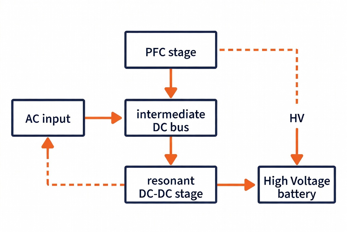
Inside a modern On-Board Charger (OBC), the Power Factor Correction (PFC) stage and the resonant DC-DC converter stage form a classic two-stage architecture that together convert grid AC power into controlled DC power for the high-voltage battery. The PFC stage is responsible for shaping the input current, achieving near-unity power factor, and generating a stable intermediate DC bus. The resonant stage then provides galvanic isolation, high-frequency energy transfer, and precise regulation of the battery charging voltage and current. This division of labor enables high efficiency, low harmonic distortion, and compliance with grid and automotive safety standards.
 |
1. The Role of the PFC Stage
The front-end Power Factor Correction (PFC) stage is the first conversion block in the OBC. Its primary functions are:
- Power Factor Correction
It forces the input current to follow the shape of the AC voltage waveform, achieving a power factor typically greater than 0.99. This minimizes reactive power drawn from the grid and reduces harmonic pollution. - AC-to-DC Conversion
The PFC converts single-phase or three-phase AC input (usually 85–265 V or higher) into a relatively stable high-voltage DC bus, commonly around 400 V. - Harmonic Suppression
By shaping the current, the PFC ensures compliance with international standards such as IEC 61000-3-2, limiting total harmonic distortion (THD).
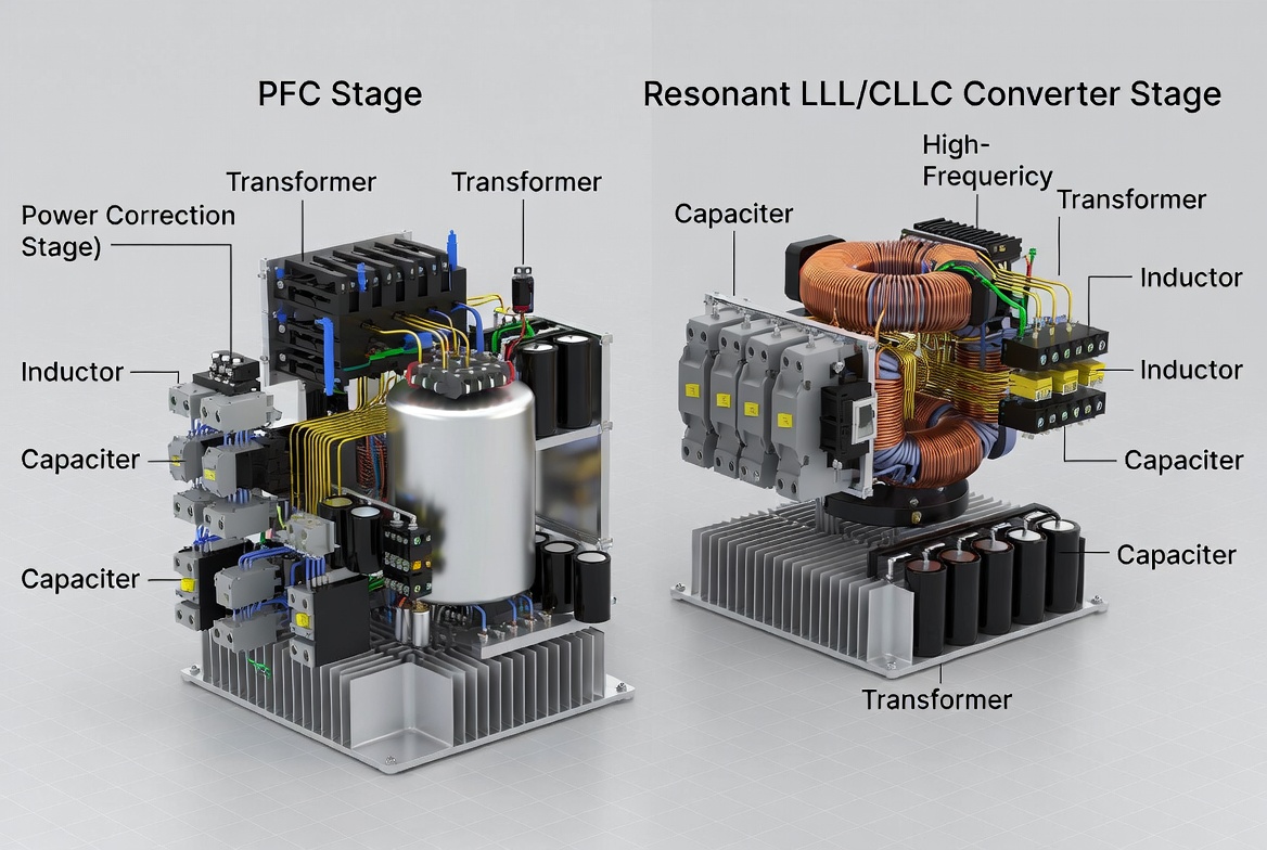
Common topologies for this stage include boost PFC, interleaved boost, and bridgeless totem-pole PFC. In higher-power or bidirectional designs, active switches replace passive diode bridges to improve efficiency and enable reverse power flow.
Ovar Tech’s OBC modules, including the 6.6 kW and 11 kW integrated solutions, employ advanced PFC designs that maintain high power factor across a wide input voltage range while supporting both unidirectional and bidirectional operation.
2. The Role of the Resonant DC-DC Stage
After the PFC creates the intermediate DC bus, the resonant converter stage performs the second conversion. Its key responsibilities are:
- Galvanic Isolation
A high-frequency transformer provides electrical isolation between the grid side and the high-voltage battery, satisfying automotive safety requirements (typically reinforced insulation rated for several kilovolts). - Voltage Matching and Regulation
The resonant stage steps the intermediate DC bus voltage up or down to match the battery voltage range (commonly 200–450 V for 400 V platforms or 400–850 V for 800 V platforms). It also regulates charging current according to Battery Management System (BMS) commands. - High Efficiency through Soft Switching
Resonant topologies such as LLC or CLLC achieve Zero-Voltage Switching (ZVS) or Zero-Current Switching (ZCS). This dramatically reduces switching losses, allowing high-frequency operation (100–500 kHz) and smaller magnetic components. - Bidirectional Capability (in advanced designs)
When a CLLC or Dual Active Bridge topology is used, the resonant stage can reverse power flow, enabling Vehicle-to-Grid (V2G) and Vehicle-to-Load (V2L) functions.
Ovar Tech’s bi-directional 11 kW OBC + 3 kW DC-DC modules utilize CLLC resonant converters, achieving peak efficiencies of up to 95.5 % while supporting both charging and energy export.
 |
3. Why the Two-Stage Architecture Is Preferred
Separating the functions into PFC and resonant stages offers several advantages:
- Each stage can be optimized independently for its specific task.
- The intermediate DC bus acts as an energy buffer, improving transient response and system stability.
- Isolation is confined to the high-frequency resonant stage, reducing the size and cost of the isolation transformer.
- Soft-switching in the resonant stage allows higher switching frequencies, resulting in higher power density.
In contrast, single-stage topologies exist but generally struggle to simultaneously achieve high power factor, isolation, and wide voltage regulation while maintaining efficiency.
4. Interaction Between the Two Stages
The PFC stage regulates the intermediate DC bus voltage (typically fixed or with a limited range), while the resonant stage handles the wide output voltage variation required by the battery. Communication between the stages and with the vehicle BMS ensures coordinated control of power, voltage, and current. Protection functions such as over-voltage, over-current, and short-circuit detection are implemented at both stages for comprehensive system safety.
5. Summary of Functional Division
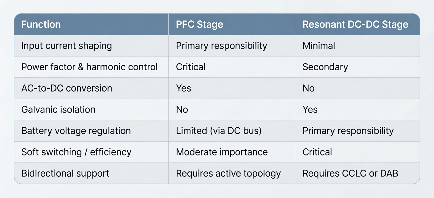 |
Conclusion
In an On-Board Charger, the PFC stage and the resonant DC-DC stage work as complementary partners. The PFC ensures clean, efficient power draw from the AC grid and creates a stable intermediate bus, while the resonant stage delivers isolated, precisely regulated power to the high-voltage battery with minimal losses. This two-stage architecture remains the industry standard for high-performance OBCs. Ovar Tech’s product portfolio, spanning 6.6 kW to 11 kW integrated and bi-directional solutions, demonstrates how carefully engineered PFC and resonant stages can deliver high efficiency, compact size, and robust reliability for commercial vehicles, passenger cars, and marine applications.
この記事を共有する